28 Results
View results:
Sort by:

Both the determination of natural vibrations and the response spectrum analysis are always performed on a linear system. If nonlinearities exist in the system, they are linearized and thus not taken into account. They are caused by, for example, tension members, nonlinear supports, or nonlinear hinges. This article shows how you can handle them in a dynamic analysis.

Plastic hinges are imperative for the Pushover Analysis (POA) as a nonlinear static method for the seismic analysis of structures. In RFEM 6, plastic hinges can be defined as member hinges. This article will show you how to define plastic hinges with bilinear properties.

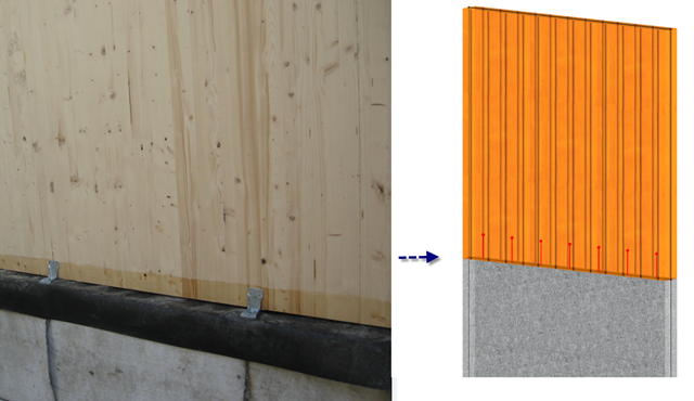
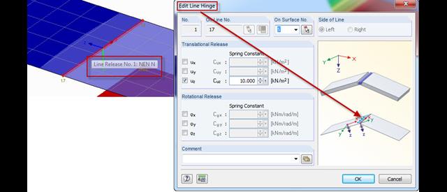
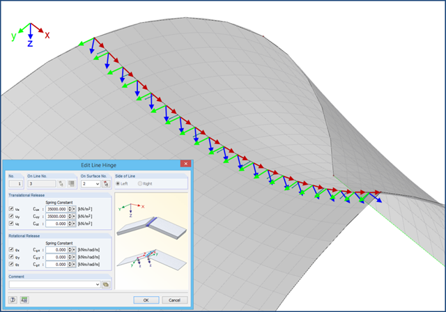
The properties of the connection between a reinforced concrete slab and a masonry wall can be correctly considered in the modeling using a special line hinge that is available in RFEM 6. This article will show you how to define this type of hinge using a practical example.

This article will show you how to properly consider the connection between surfaces that touch each other on one line with the help of line hinges in RFEM 6.

Complex structures are assemblies of structural elements with various properties. However, certain elements can have the same properties in terms of supports, nonlinearities, end modifications, hinges, and so on, as well as design (for example, effective lengths, design supports, reinforcement, service classes, section reductions, and so on). In RFEM 6, these elements can be grouped on the basis of their shared properties and thus can be considered together for both modeling and design.

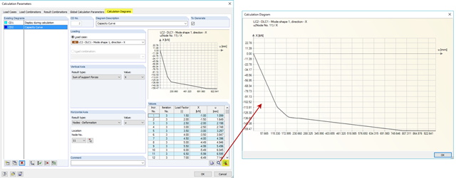
To simulate a support clearance in a connection between members, you can use the "Diagram" function for member hinges. To use this function, first define the relevant degree of freedom as release. Then, you can select the "Diagram" function from the drop‑down list.

With the RF-/TIMBER Pro add-on module, you can perform the vibration design known from DIN 1052 for the design according to EN 1995-1-1. In this design, the deflection under permanent and quasi-permanent action at the ideal one‑span beam may not exceed the limit value (6 mm according to DIN 1052). If you consider the relation between the natural frequency and the deflection for a hinged single-span beam subjected to a constant distributed load, the 6 mm limit value results in a minimum natural frequency of about 7.2 Hz.

In RF‑/STEEL EC3, you can assign the same input data to several members or sets of members at the same time. The simultaneous assignment of the input data is possible for intermediate supports, effective lengths, nodal supports, member end hinges, and shear panel and rotational restraint.

The most common causes of unstable models are failing member nonlinearities such as tension members. As the simplest example, there is a frame with supports on the column footing and moment hinges on the column head. This unstable system is stabilized by a cross bracing of tension members. In the case of load combinations with horizontal loads, the system remains stable. However, if it is loaded vertically, both tension members fail and the system becomes unstable, which causes a calculation error. You can avoid such an error by selecting the exceptional handling of failing members under "Calculate" → "Calculation Parameters" → "Global Calculation Parameters".

In RFEM 5 and RSTAB 8, it is possible to assign nonlinearities to member hinges. In addition to the nonlinearities "Fixed if" and "Partial activity", you can select "Diagram". If you select the "Diagram" option, you have to specify the according settings for the activity of the member hinge. For the individual definition points, it is necessary to specify the abscissa and ordinate values (deformations or rotations and the according internal forces) that define the hinge.

The shear force resistance VRd,c without computational shear force reinforcement according to 6.2.2 of EN 1992-1-1 [1] or 10.3.3 of DIN 1045-1 [2] is calculated depending on the longitudinal reinforcement ratio. If the required longitudinal reinforcement from the bending design is used for the calculation of VRd,c, this leads to an underestimation of the shear force resistance without shear reinforcement in the vicinity of the hinged end supports. In contrast to the shear force, the required bending reinforcement decreases in the direction of the support. Furthermore, the actually inserted longitudinal reinforcement usually deviates significantly from the required bending reinforcement in the end support area (for example, in the case of non-staggered beam reinforcement).
When modeling frame structures, RFEM and RSTAB provide various options for controlling the transfer of internal forces and moments at the connection points of members. You can use the member types to determine whether only forces act on the connected members, or whether moments act on them as well. In addition, you can use hinges to exclude specific internal forces from the transfer. One special form is scissor hinges, which allow for realistic modeling of roof structures, for example.
In this technical article, a hinged column with a centrally acting axial force will be designed by means of the RF-/STEEL EC3 add-on module according to EN 1993-1-2. We will use the National Annex of Germany here.

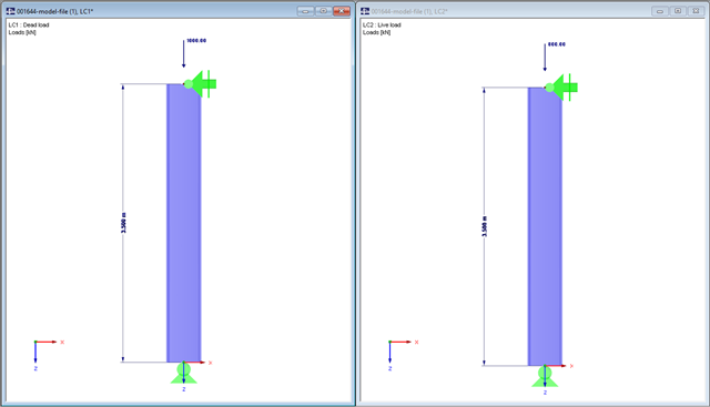
In this technical article, a hinged column with a centrally acting axial force and a line load acting on the strong axis will be designed by means of the RF-/STEEL EC3 add-on module according to EN 1993-1-1.
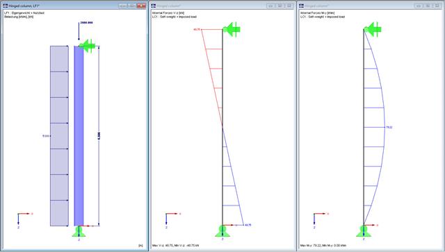
In this technical article, a hinged column with a centrally acting axial force and a linear load that acts on the major axis are designed according to EN 1993-1-1 with the aid of the RF-/STEEL EC3 add-on module. The column head and column base are assumed as a lateral and torsional restraint. The column is not held against rotation between the supports. The cross-section of the column is an HEB 360 from S235.

RFEM and RSTAB offer different options to model bored piles. One option is to display bored piles as single-valued supports or hinged columns. Another option is realistic modeling while taking the soil into account by means of applying a member elastic foundation. The two following examples will describe it in detail. However, pile base resistance, skin friction, and soil layers are not considered in this technical article.
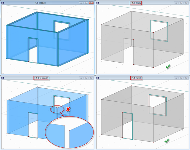
This article deals with considering end releases between surfaces with line hinges and line releases. End releases between surfaces are taken into account using line releases as well as line hinges. The examples are joints in reinforced concrete structures and frame joints in cross-laminated timber structures.
![System and Loading According to [1]](/en/webimage/009455/2418877/01-en-png.png?mw=640&hash=c76563b459152b19c98197ea6ba342be89d9a5bc)
The product range of Dlubal Software contains various modules for design of steel and timber connections. The RF-/JOINTS Steel – Column Base add-on module allows you to analyse footings of hinged or restrained steel column bases. The fastener selection, foundation geometry, and material quality are crucial for the cost-effective and safe design of the column base.
![System and Loading According to [1]](/en/webimage/009634/2419765/01-en-png-png.png?mw=640&hash=5e657e3feb5c1bb6d21727468dd85d91e1c9f29f)
A structural analysis does not only determine and design internal forces and deformations. It also ensures that the forces and moments in a structure are generated in a reliable way and applied to the foundation. Dlubal Software provides a wide range of products for the structural analysis and design of steel and timber connections. The RF-/JOINTS Steel – Column Base add-on module allows you to design footings of hinged and restrained column bases. The design can be performed for column base plates with or without stiffeners.
Pushover analysis is a nonlinear structural calculation for seismic analysis of structures. The load pattern is inferred from the dynamic calculation of equivalent loads. These loads are increased incrementally until global failure of the structure occurs. The nonlinear behaviour of a building is usually represented by using plastic hinges.
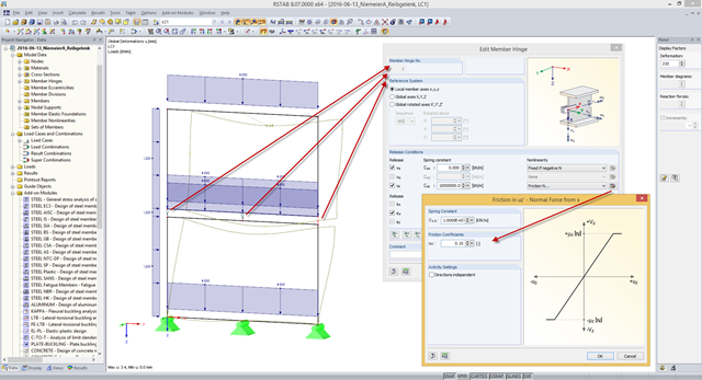
Some compound beam structures, such as stacked containers or retracted telescopic bars, transfer the forces in the connection between the components by friction. The load-bearing capacity of such a connection depends on the effective axial force perpendicular to the friction plane and on the friction coefficients between both friction surfaces. For example, the more the friction surfaces are compressed, the more horizontal shear force can be transferred by the friction surfaces (static friction).
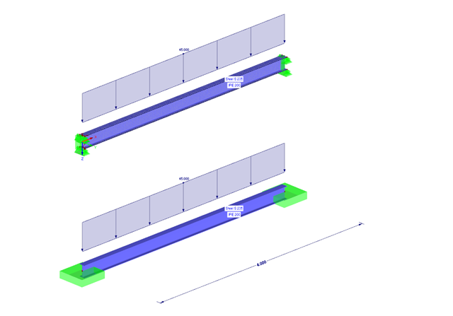
The following example presents a comparison between a shell model and a simple member model performed in RFEM. In the case of the shell model, there is a beam suspended in surfaces, which is modeled with restraints on both sides due to the boundary conditions. This is a statically indeterminate system that forms plastic hinges when overloaded. The comparison is carried out on a member model that has the same boundary conditions as the shell model.
In order to facilitate the selection of the corresponding line release, the axis system of the line release appears when selecting a line release. In the case of a line hinge, the orientation is often different; therefore, the representation has been improved in the pre‑selection for line hinges.
In RFEM and RSTAB, several interfaces are available. The DSTV interface (*.stp) is the most convenient for importing beam structures, since supports, hinges, loads, and load combinations are also transferred, in addition to the general topology.
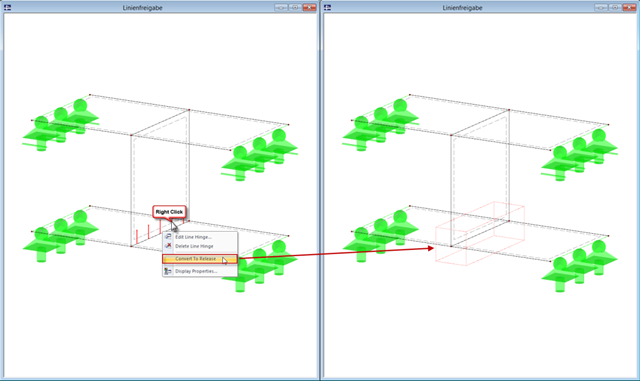
When using line hinges in a structure, you can convert them quickly to line releases in order to consider the nonlinear effects in the structure.
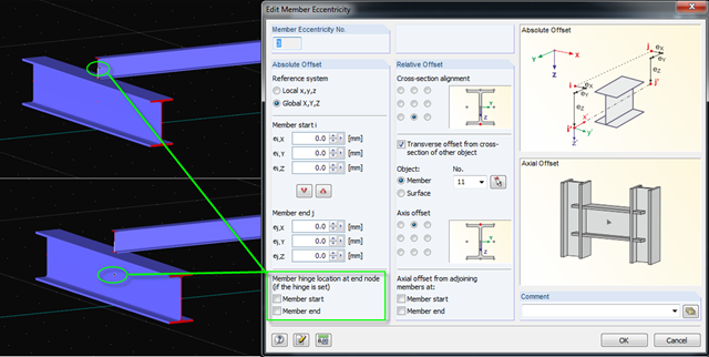
When modeling eccentric members with member hinges, RFEM provides the option to assign the hinge to the start or end of the member eccentricity. There is another option for creating and displaying the structural system more precisely in the design.

For structural reasons, shear connections usually include fin plates or flange angles. Main and secondary beams arranged on the top edge require notching or long fin plates. Hinged end plate connections are often welded to the web.
If it is impossible to transfer all internal forces from one surface to the next, you have to arrange a line hinge. To do this, use the "Edit Surface" dialog box, "Hinges" tab.